Aller au contenu

Examples of synthesizable VHDL

The examples presented in this document are all inferred on the dedicated resources of FPGA (adder, counter, RAM...). They are synthesizable VHDL codes that can be used to describe a circuit that we want to implement on FPGA or ASIC.

Process

Processes in VHDL are used to describe the operation of a part of a circuit, in particular circuits (using a clock) or complex combinatorial circuits. In processes it is possible to use conditional structures such as the classic if/elsif/else and case.

A process has a sensitivity list, i.e. a list of input signals. The process reacts to the changes of state of the signals that are present in the sensitivity list. It is crucial to fill in this sensitivity list correctly.

On the other hand, a signal that is only updated in the process does not need to be present in the sensitivity list.

Synchronous process

A synchronous process has, as its name indicates, an operation synchronized by the events affecting a signal in its sensitivity list. We call this signal the clock, and most often processes of this type are synchronized on the rising edge of the clock, i.e. the passage from state 0 to state 1. The process updates the signals that it controls only at the time of the rising edge, whatever the evolution of the signals used in this process. For this reason, the sensitivity list of a synchronous process is a bit special. It contains only the clock and possibly a reset in the case of an asynchronous reset. Even if signals are read or used in the synchronous part, it is not necessary to put them in the sensitivity list.

 1
 2
 3
 4
 5
 6
 7
 8
 9
10
11
process(I_Clock)  -- sensitivity list in brackets, consisting of a clock and eventually a reset
begin

  if(rising_edge(I_Clock)) then
    if I_Reset = '1' then   -- active high synchronous reset
        -- what happens if the reset is active
    else
        -- what happens at the time of a clock rising edge without reset
    end if;
  end if;
end process;

Is the asynchronous reset mandatory ?

The asynchronous reset is often present in VHDL synchronous process. But in some if not most FPGA designs, it is vastly optionnal. Its presence might even be a nuisance. A really good overview of the question is presented here Get your Priorities Right — Make your Design Up to 50% Smaller https://www.xilinx.com/support/documentation/white_papers/wp275.pdf

Asynchronous process

The asynchronous process, being by definition combinatorial, must react immediately to the change of state of any of its input signals. It is therefore imperative to fill in the sensitivity list exhaustively.

 1
 2
 3
 4
 5
 6
 7
 8
 9
10
11
process(S1,S2,S3,S3,S5,S6)
begin
  -- description of the circuit using the signals in the sensitivity list. For example :
  if(S1 = '1')then
    S7 <= S5 xor S6; -- S7 does not have to be in the sensitivity list, it is not read
  elsif(S2 = '1')then
    S7 <= S3;
  else
    S7 <= S4;
  end if;
end process;

Implicit process

It is possible to describe the operation of a circuit outside an explicit process. This is called an implicit process. Implicit processes are used when it is not necessary to use a process as such. Putting a permanent connection (assignment) between two signals in an explicit process is of no interest, it is done outside:

 1
 2
 3
 4
 5
 6
 7
 8
 9
10
11
process(...)
begin
    ...
end process;

A <= B and C;  -- Implicit process here

process(...)
begin
    ...
end process;

Conditionnal structures

if, elsif, else

This kind of conditionnal structure is always inside an explicit process :

 1
 2
 3
 4
 5
 6
 7
 8
 9
10
11
12
13
14
15
16
17
18
19
20
21
22
23
24
25
26
27
signal A : std_logic_vector(2 downto 0);
signal S : std_logic_vector(2 downto 0);
--
process(A)
begin
    if (A = "000") then
        S <= "000";
    elsif (A = "001") then
        S <= "001";
    elsif (A = "001") then
        S <= "011";
    elsif (A = "010") then
        S <= "011";
    elsif (A = "011") then
        S <= "010";
    elsif (A = "100") then
        S <= "110";
    elsif (A = "101") then
        S <= "111";
    elsif (A = "110") then
        S <= "110";
    elsif (A = "111") then
        S <= "100";
    else
        S<="000";
    end if;
end process;

Warning

Never forget the else at the end when in a combinatorial process

case

This kind of conditionnal structure is always inside an explicit process as well :

 1
 2
 3
 4
 5
 6
 7
 8
 9
10
11
12
13
14
15
Process(A)
Begin
    Case A is
        when "000"  => S <= "000";
        when "001"  => S <= "001";
        when "001"  => S <= "011";
        when "010"  => S <= "011";
        when "011"  => S <= "010";
        when "100"  => S <= "110";
        when "101"  => S <= "111";
        when "110"  => S <= "110";
        when "111"  => S <= "100";
        when others => S <= "000";
    end case;
end process ;

Warning

Never forget the when others at the end when in a combinatorial process

Conditionnal assignment when else

This kind of conditionnal structure is described as implicit process :

1
2
3
4
5
6
7
8
9
S <= "000" when(A = "000")else
     "001" when(A = "001")else
     "011" when(A = "010")else
     "010" when(A = "011")else
     "110" when(A = "100")else
     "111" when(A = "101")else
     "110" when(A = "110")else
     "100" when(A = "111")else
     "000";

This type of assignment is very convenient and readable for the assignment of a binary signal.

1
W <= '1' when(A = "01110" or B = '1' and C = '1')else '0';

Warning

Never forget the else at the end.

Conditionnal assignment with select

 1
 2
 3
 4
 5
 6
 7
 8
 9
10
with A select S <=
    "000" when "000",
    "001" when "001",
    "011" when "010",
    "010" when "011",
    "110" when "100",
    "111" when "101",
    "110" when "110",
    "100" when "111",
    "000" when others;

Warning

Never forget the when others at the end.

Type conversion with the numeric_std library

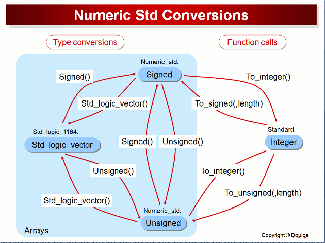
It is necessary to use an external package (preferably standardized) that defines the operators. This is the role of the numeric_std library. It will then be easy to switch from one format to another.

  • to_integer : Transforms a vector of type signed or unsigned to integer
  • to_unsigned : Transforms a signal of type integer, into a vector of type unsigned. Also allows to extend the format of an unsigned vector
  • to_signed : Same property as the src_vhdl[:exports code]{to_unsigned} function for signed numbers.
1
2
3
4
5
6
7
8
9
integer_Signal <= to_integer(unsigned_Signal);
integer_Signal <= to_integer(signed_Signal);
unsigned_Signal <= to_unsigned(a_natural_signal , length_of_unsigned_Signal);
unsigned_Signal <= to_unsigned(an_integer_signal , length_of_unsigned_Signal);
signed_Signal   <= to_signed(another_natural_signal   , length_of_signed_Signal);
signed_Signal   <= to_signed(another_integer_signal   , length_of_signed_Signal);
--
signal B : signed(3 downto 0) ; -- 4 bits width
A < = to_unsigned(B , 5) ;  -- A is 5 bits wide

Conversion with numeric_std package functions (source: Doulos)

Conversion with `numeric_std` package functions (source: Doulos)

Numeral assignement with numeric_std

 1
 2
 3
 4
 5
 6
 7
 8
 9
10
11
12
13
signal AU : unsigned(3 downto 0); -- 4 bits
signal BU : unsigned(3 downto 0); -- 4 bits
signal SU : unsigned(7 downto 0); -- 8 bits
signal AS : signed(3 downto 0);
signal BS : signed(3 downto 0);
signal SS : signed(7 downto 0);
--
AU <= to_unsigned(15, 4);
BU <= to_unsigned(15, 4);
AS <= to_signed(7, 4);
BS <= to_signed(-8, 4);
AI <= -16;
BI <= -16;

Useful function from numeric_std

resize

The resize function is used to expand the size of an unsigned or a signed signal. This function is signed aware and will expand the MSB to preserve the signe of the signal. This function is particularly useful when doing arithmetic to manage overflow.

1
2
3
4
5
6
signal S : signed(11 downto 0);
signal A : signed 5 downto 0);

...

S <= resize(A, 12);  -- resize A to be on 12 bits

Multiplexer

Multiplexer

Multiplexeur

Described with a case structure:

 1
 2
 3
 4
 5
 6
 7
 8
 9
10
11
12
13
14
process(E1,E2,...,En,Sel)
begin
    case Sel is
        when "0...00" =>
            S <= E1;
        when "0...01" =>
            S <= E2;
        .
        .
        .
        when others =>
            S <= En;
    end case;
end process;

Described with a when else structure:

1
2
3
4
5
6
S <= E1 when(Sel = "0...00")else
     E2 when(Sel = "0...01")else
     .
     .
     En-1 when (Sel = "......") else
     En;

Adder

Adder

Adder

Without Carry-out:

1
2
3
4
5
signal A : signed (3 downto 0);
signal B : signed (3 downto 0);
signal S : signed (3 downto 0);
--
S <= A + B ; -- no overflow management

With Carry-out:

1
2
3
4
5
signal A : signed (3 downto 0);
signal B : signed (3 downto 0);
signal S : signed (4 downto 0);
--
S <= resize(A, S'length) + resize(B, S'length); -- overflow managed

The size of the result of an addition of two operand is the size of the largest operand plus one.

Multiplier

Multiplier

Multiplier
 1
 2
 3
 4
 5
 6
 7
 8
 9
10
11
12
13
signal AU : unsigned(3 downto 0); -- 4 bits
signal BU : unsigned(3 downto 0); -- 4 bits
signal SU : unsigned(7 downto 0); -- 8 bits
signal AS : signed(3 downto 0);
signal BS : signed(3 downto 0);
signal SS : signed(7 downto 0);
signal AI : integer range -16 to 15;
signal BI : integer range -16 to 15;
signal SI : integer range -512 to 511;
--
SU <= AU * BU;
SS <= AS * BS;
SI <= AI * BI;

Register

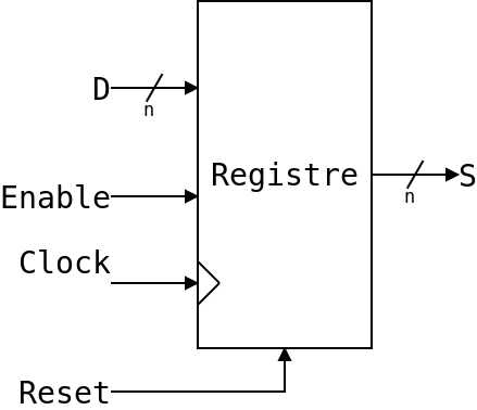
Here is one example of a register with synchronous init and enable. Whenever the init input is high and there is a rising edge of the clock, the value stored in the O_S signal will be set to "00000000". When the init is low, the load is high and there is a rising edge of the clock, the O_S signal will be set to the value present in I_D.

Register with asynchronous reset and synchronous enable

Register with asynchronous reset and synchronous enable
Register with **Synchronous** Reset
 1
 2
 3
 4
 5
 6
 7
 8
 9
10
11
12
13
14
15
16
17
18
architecture archi of Registre is

signal SR_Register : std_logic_vector(7 downto 0) := (others => '0');

begin

  process(I_Clock)
  begin
    if(rising_edge(I_Clock))then
      if(I_init = '1')then
        SR_Register <= (others => '0');
      elsif(I_Load = '1')then
        SR_Register <= I_InputData;
      end if;
    end if;
  end process;

end archi;

A register can be seen as a row of flip-flop, each one storing a bit of the signal (8 bits here).

Shift register

Here is one example of a shift register with a parallel load.

 1
 2
 3
 4
 5
 6
 7
 8
 9
10
11
12
13
14
15
16
17
18
19
20
21
22
23
architecture archi of RegistreDecalage is

  signal SR_Reg : std_logic_vector(7 downto 0);

begin

  process(I_Clock)
  begin
    if(rising_edge(I_Clock))then
      if(I_Enable = '1')then
        if(I_Load = '1')then
          SR_Reg <= I_D;
        else
          SR_Reg(6 downto 0) <= SR_Reg(7 downto 1);
          SR_Reg(7)          <= '0';
        end if;
      end if;
    end if;
  end process;

  O_S <= SR_Reg(0);

end archi;

The shift can be done the same way with arrays.

Counters

Example of a modulo 112 counter with synchronous init, enable and load.

Using unsigned type

 1
 2
 3
 4
 5
 6
 7
 8
 9
10
11
12
13
14
15
16
17
18
19
20
21
22
23
24
25
26
architecture archi_Counter of Counter is

  signal SR_Counter : unsigned(7 downto 0) := (others := '0');

begin

  process (I_Clock) is
  begin
    if(rising_edge(I_Clock))then
      if(I_Init = '1')then
        SR_Counter <= (others => '0');
      elsif(I_Enable = '1')then
        if(I_Load = '1')then
          SR_Counter <= unsigned(I_DLoad);
        elsif(SR_Counter >= to_unsigned(111 ,8))then
          SR_Counter <= (others => '0');
        else
          SR_Counter <= SR_Counter + 1;
        end if;
      end if;
    end if;
  end process;

  O_Count <= std_logic_vector(SR_Counter);

end architecture archi_Counter;

Using integer type:

 1
 2
 3
 4
 5
 6
 7
 8
 9
10
11
12
13
14
15
16
17
18
19
20
21
22
23
24
25
26
architecture archi_Counter of Counter is

  signal SR_Counter : integer range 0 to 111 := 0;

begin

  process (I_Clock)
  begin
    if (rising_edge(I_Clock))then
      if(I_Init = '1')then
        SR_Counter <= 0;
      elsif(I_Enable = '1')then
        if(I_Load = '1')then
          SR_Counter <= to_integer(unsigned(I_DLoad));
        elsif(SR_Counter >= 111)then
          SR_Counter <= 0;
        else
          SR_Counter <= SR_Counter + 1;
        end if;
      end if;
    end if;
  end process;

  O_Count <= std_logic_vector(to_unsigned(SR_Counter , 8));

end architecture archi_Counter;

RAM (Random access memory)

Most FPGAs include specific blocks dedicated to implement RAMs in an optimal way. These are not special LUTs, but directly RAMs that can be used if the VHDL is written correctly. See section

Example of RAM VHDL description infered on block RAM

Finite State Machine (FSM)

Even at a relatively low level of complexity, a circuit is often divided into several main blocks. Most of the time an operative unit, containing all the arithmetic operators, processing units etc, and a control part, implemented by a state machine.

A FSM allows to :

  • Indicate what state the system is in
  • evaluate what will be the future state of the system according to the present state and the values present on the input signals
  • drive the control signals of the operative part and, if necessary, of the system's outputs according to the present and eventually states of the inputs.

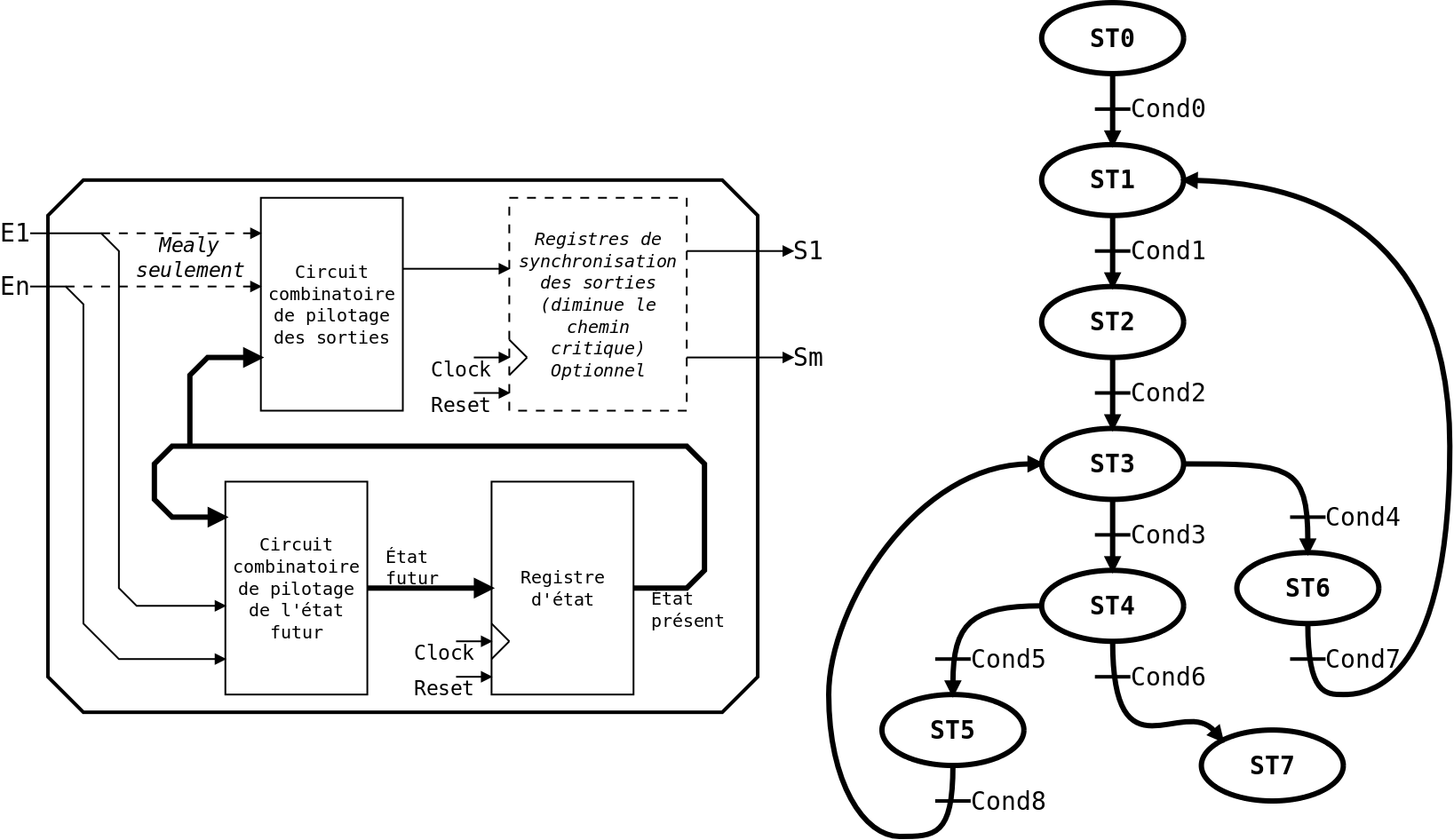
We distinguish two types of FSM, Moore's FSM whose output signals depend only on the present state, and Mealy's machines whose output signals depend on the present and input states. The Mealy machines have the advantage of being more reactive because we can make the output signals evolve not only according to the present state, but also according to the inputs, thus on the transitions between states. Speaking of output signals, they can be synchronized or not. If they are not synchronized, the FSM will be more reactive, but will introduce a longer logic path, thus potentially a lower operating frequency. If they are, the FSM will be less reactive, but will be better in terms of achievable frequency.

Moore Mealy
Asynchronous outputs 1 cycle response time, Low frequency 0 cycle response time, Low frequency
Synchronous outputs 2 cycle response time, High frequency 1 cycle response time, High frequency

FSM

FSM

Three process way

Regarding the previous architecture, the most intuitive way of describing a FSM in VHDL is to use three processes :

  • The first one is a synchronous process used to update the present state register with the value of the futur state
  • The second one is a combinatorial process used to compute the futur state based on the present state and the inputs
  • The third one is also a combinatorial process used to compute the values of the outputs based on the present state alone in the case of a Moore FSM, or on the present state and the inputs in the case of a Mealy FSM
  1
  2
  3
  4
  5
  6
  7
  8
  9
 10
 11
 12
 13
 14
 15
 16
 17
 18
 19
 20
 21
 22
 23
 24
 25
 26
 27
 28
 29
 30
 31
 32
 33
 34
 35
 36
 37
 38
 39
 40
 41
 42
 43
 44
 45
 46
 47
 48
 49
 50
 51
 52
 53
 54
 55
 56
 57
 58
 59
 60
 61
 62
 63
 64
 65
 66
 67
 68
 69
 70
 71
 72
 73
 74
 75
 76
 77
 78
 79
 80
 81
 82
 83
 84
 85
 86
 87
 88
 89
 90
 91
 92
 93
 94
 95
 96
 97
 98
 99
100
101
102
103
104
105
106
107
108
109
110
111
112
113
114
115
116
117
118
119
120
121
122
123
124
125
126
127
128
129
130
131
132
133
134
135
136
137
138
139
140
141
142
143
144
145
146
147
148
149
150
151
152
library ieee;
use ieee.std_logic_1164.all;
use ieee.numeric_std.all;

entity fsm is
    port (
        I_Clock : in  std_logic;
        I_reset : in  std_logic;
        I_1     : in  std_logic;
        I_2     : in  std_logic;
        I_3     : in  std_logic;
        I_4     : in  std_logic;
        I_5     : in  std_logic;
        O_1     : out std_logic;
        O_2     : out std_logic;
        O_3     : out std_logic;
        O_4     : out std_logic
        );
end entity fsm;

architecture a_fsm of fsm is

    type T_State is (ST0, ST1, ST2, ST3, ST4, ST5, ST6, ST7);
    signal SR_present : T_State;
    signal SC_futur   : T_State;

begin

    process(I_Clock, I_reset) is
    begin
        if I_reset = '1' then
            SR_present <= ST0;
        elsif(rising_edge(I_Clock)) then
            SR_present <= SC_futur;
        end if;
    end process;


    process(SR_present, I_1, I_2, I_3, I_4, I_5)
    begin
        case SR_present is
            when ST0 =>
                SC_futur <= ST1;

            when ST1 =>
                if(I_1 = '1')then       --Cond1
                    SC_futur <= ST2;
                else
                    SC_futur <= ST1;
                end if;

            when ST2 =>
                if(I_2 = '1' and I_4 = '0')then  --Cond2
                    SC_futur <= ST3;
                else
                    SC_futur <= ST2;
                end if;

            when ST3 =>
                if(I_3 = '1')then       --Cond3
                    SC_futur <= ST4;
                elsif(I_2 = '1')then    --Cond4
                    SC_futur <= ST6;
                else
                    SC_futur <= ST3;
                end if;

            when ST4 =>
                if(I_1 = '0' and I_2 = '1')then  --Cond5
                    SC_futur <= ST5;
                elsif(I_5 = '1')then
                    SC_futur <= ST7;
                else
                    SC_futur <= ST4;
                end if;

            when ST5 =>
                if(I_5 = '1')then       --Cond8
                    SC_futur <= ST3;
                else
                    SC_futur <= ST5;
                end if;

            when ST6 =>
                if(I_4 = '1' and not (I_2 = '1' xor I_3 = '0'))then  --Cond7
                    SC_futur <= ST1;
                else
                    SC_futur <= ST6;
                end if;

            when ST7 =>
                SC_futur <= ST7;

            when others =>
                SC_futur <= ST0;

        end case;
    end process;


    process(SR_present, I_1, I_2, I_3, I_4, I_5)
    begin

        -- default output values
        O_1 <= '0';
        O_2 <= '0';
        O_3 <= '0';
        O_4 <= '0';

        case SR_present is

            when ST2 =>
                O_1 <= '1';                      --moore output (depending on state only)
                if(I_2 = '1' and I_4 = '0')then  --Cond2
                    O_2 <= '1';                  --mealy output (depending on state and input)
                else
                    O_2 <= '0';                  --mealy output (depending on state and input)
                end if;

            when ST3 =>
                O_1 <= '1';
                O_3 <= '1';

            when ST4 =>
                O_2 <= '1';
                O_3 <= '1';
                if(I_1 = '0' and I_2 = '1')then  --Cond5
                    O_4 <= '1';
                else
                    O_4 <= '0';
                end if;

            when ST5 =>
                O_1 <= '1';

            when ST6 =>
                O_1 <= '1';
                if(I_4 = '1' and not (I_2 = '1' xor I_3 = '0'))then  --Cond7
                    O_2 <= '1';
                else
                    O_2 <= '0';
                end if;

            when ST7 =>
                SR_present <= ST7;

            when others =>
                SR_present <= ST0;

        end case;
    end process;
end a_fsm;

The last process, managing the outputs, can be split in several explicit or implicit processes for more convenience.

One synchronous process way

  1
  2
  3
  4
  5
  6
  7
  8
  9
 10
 11
 12
 13
 14
 15
 16
 17
 18
 19
 20
 21
 22
 23
 24
 25
 26
 27
 28
 29
 30
 31
 32
 33
 34
 35
 36
 37
 38
 39
 40
 41
 42
 43
 44
 45
 46
 47
 48
 49
 50
 51
 52
 53
 54
 55
 56
 57
 58
 59
 60
 61
 62
 63
 64
 65
 66
 67
 68
 69
 70
 71
 72
 73
 74
 75
 76
 77
 78
 79
 80
 81
 82
 83
 84
 85
 86
 87
 88
 89
 90
 91
 92
 93
 94
 95
 96
 97
 98
 99
100
101
102
103
104
105
106
107
108
109
110
111
112
113
library ieee;
use ieee.std_logic_1164.all;
use ieee.numeric_std.all;

entity fsm is
    port (
        I_Clock : in  std_logic;
        I_reset : in  std_logic;
        I_1     : in  std_logic;
        I_2     : in  std_logic;
        I_3     : in  std_logic;
        I_4     : in  std_logic;
        I_5     : in  std_logic;
        O_1     : out std_logic;
        O_2     : out std_logic;
        O_3     : out std_logic;
        O_4     : out std_logic);
end entity fsm;

architecture a_fsm of fsm is

    type T_State is (ST0, ST1, ST2, ST3, ST4, ST5, ST6, ST7);
    signal SR_present : T_State;

begin

    process (I_Clock, I_reset) is
    begin
        if I_reset = '1' then
            O_1        <= '0';
            O_2        <= '0';
            O_3        <= '0';
            O_4        <= '0';
            SR_present <= ST0;
        elsif(rising_edge(I_Clock)) then
            case SR_present is
                when ST0 =>
                    SR_present <= ST1;

                when ST1 =>
                    if(I_1 = '1')then   --Cond1
                        SR_present <= ST2;
                    else
                        SR_present <= ST1;
                    end if;

                when ST2 =>
                    O_1 <= '1';                      --moore output (depending on state only)
                    if(I_2 = '1' and I_4 = '0')then  --Cond2
                        SR_present <= ST3;
                        O_2        <= '1';           --mealy output (depending on state and input)
                    else
                        SR_present <= ST2;
                        O_2        <= '0';           --mealy output (depending on state and input)
                    end if;

                when ST3 =>
                    O_1 <= '1';
                    O_3 <= '1';
                    if(I_3 = '1')then     --Cond3
                        SR_present <= ST4;
                    elsif(I_2 = '1')then  --Cond4
                        SR_present <= ST6;
                    else
                        SR_present <= ST3;
                    end if;

                when ST4 =>
                    O_2 <= '1';
                    O_3 <= '1';
                    if(I_1 = '0' and I_2 = '1')then  --Cond5
                        SR_present <= ST5;
                        O_4        <= '1';
                    elsif(I_5 = '1')then
                        SR_present <= ST7;
                        O_4        <= '0';
                    else
                        SR_present <= ST4;
                        O_4        <= '0';
                    end if;

                when ST5 =>
                    O_1 <= '1';
                    if(I_5 = '1')then   --Cond8
                        SR_present <= ST3;
                    else
                        SR_present <= ST5;
                    end if;

                when ST6 =>
                    O_1 <= '1';
                    if(I_4 = '1' and not (I_2 = '1' xor I_3 = '0'))then  --Cond7
                        SR_present <= ST1;
                        O_2        <= '1';
                    else
                        SR_present <= ST6;
                        O_2        <= '0';
                    end if;

                when ST7 =>
                    SR_present <= ST7;
                    O_1        <= '1';
                    O_2        <= '1';
                    O_3        <= '1';

                when others =>
                    SR_present <= ST0;

            end case;
        end if;
    end process;

end architecture a_fsm;

Component Instantiation

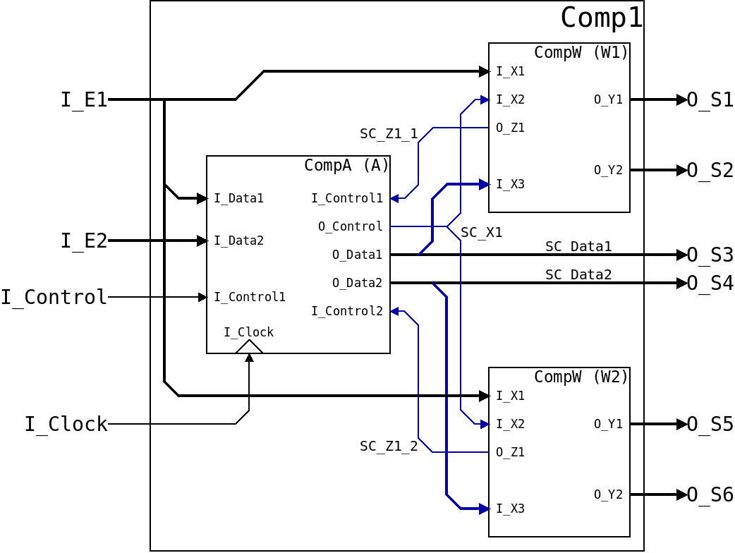
To create a component, it is often very interesting to split it into sub-components. Once the subcomponents have been created and tested, they must be assembled. The use of a sub-component in the current component is called an instantiation, we can use one or multiple instances of a sub-component. Once the sub-components are instantiated, they must be connected to the inputs/outputs/signals of the current component. In this case we speak of structural description.

Component Instantiation

Component Instantiation
  1
  2
  3
  4
  5
  6
  7
  8
  9
 10
 11
 12
 13
 14
 15
 16
 17
 18
 19
 20
 21
 22
 23
 24
 25
 26
 27
 28
 29
 30
 31
 32
 33
 34
 35
 36
 37
 38
 39
 40
 41
 42
 43
 44
 45
 46
 47
 48
 49
 50
 51
 52
 53
 54
 55
 56
 57
 58
 59
 60
 61
 62
 63
 64
 65
 66
 67
 68
 69
 70
 71
 72
 73
 74
 75
 76
 77
 78
 79
 80
 81
 82
 83
 84
 85
 86
 87
 88
 89
 90
 91
 92
 93
 94
 95
 96
 97
 98
 99
100
101
102
103
104
105
106
107
108
109
110
111
112
113
114
115
116
library ieee;
use ieee.std_logic_1164.all;
use ieee.numeric_std.all;

entity Comp1 is
  generic(
    G_SizeInput : natural;
    G_SizeS1    : natural;
    G_SizeS2    : natural;
    G_SizeS3    : natural);
  port(
    I_Clock   : in  std_logic;
    I_E1      : in  std_logic_vector(G_SizeInput-1 downto 0);
    I_E2      : in  std_logic_vector(G_SizeInput-1 downto 0);
    I_Control : in  std_logic;
    O_S1      : out std_logic_vector(G_SizeS1-1 downto 0);
    O_S2      : out std_logic_vector(G_SizeS2-1 downto 0);
    O_S3      : out std_logic_vector(G_SizeS3-1 downto 0);
    O_S4      : out std_logic_vector(G_SizeS3-1 downto 0);
    O_S5      : out std_logic_vector(G_SizeS1-1 downto 0);
    O_S6      : out std_logic_vector(G_SizeS2-1 downto 0));
end entity Comp1;

architecture archi_Comp1 of Comp1 is

  component CompA is
    generic(
      G_Data : natural;
      G_Out  : natural);
    port(
      I_Clock    : in  std_logic;
      I_Data1    : in  std_logic_vector(G_Data-1 downto 0);
      I_Data2    : in  std_logic_vector(G_Data-1 downto 0);
      I_Control1 : in  std_logic;
      I_Control2 : in  std_logic;
      O_Control  : out std_logic;
      O_Data1    : out std_logic_vector(G_Out-1 downto 0);
      O_Data2    : out std_logic_vector(G_Out-1 downto 0));
  end component;

  component CompW is
    generic(
      G_X1 : natural;
      G_X3 : natural;
      G_Y1 : natural;
      G_Y2 : natural);
    port(
      I_X1 : in  std_logic_vector(G_X1-1 downto 0);
      I_X2 : in  std_logic;
      I_X3 : in  std_logic_vector(G_X3-1 downto 0);
      O_Z1 : out std_logic;
      O_Y1 : out std_logic_vector(G_Y1-1 downto 0);
      O_Y2 : out std_logic_vector(G_Y2 downto 0));
  end component;

  signal SC_Z1_1  : std_logic;
  signal SC_Z1_2  : std_logic;
  signal SC_Data1 : std_logic_vector(G_SizeS3-1 downto 0);
  signal SC_Data2 : std_logic_vector(G_SizeS3-1 downto 0);
  signal SC_X1    : std_logic;

begin

  A : CompA
    generic map (
      G_Data => G_SizeInput,
      G_Out  => G_SizeS3)
    port map (
      I_Clock    => I_Clock,
      I_Data1    => I_E1,
      I_Data2    => I_E2,
      I_Control1 => SC_Z1_1,
      I_Control2 => SC_Z1_2,
      O_Control  => SC_X1,
      O_Data1    => SC_Data1,
      O_Data2    => SC_Data2);


  W1 : CompW
    generic map (
      G_X1 => G_SizeInput,
      G_X3 => G_SizeS3,
      G_Y1 => G_SizeS1,
      G_Y2 => G_SizeS2)
    port map (
      I_X1 => I_E1,
      I_X2 => SC_X1,
      I_X3 => SC_Data1,
      O_Z1 => SC_Z1_1,
      O_Y1 => O_S1,
      O_Y2 => O_S2);

  W2 : CompW
    generic map (
      G_X1 => G_SizeInput,
      G_X3 => G_SizeS3,
      G_Y1 => G_SizeS1,
      G_Y2 => G_SizeS2)
    port map (
      I_X1 => I_E1,
      I_X2 => SC_X1,
      I_X3 => SC_Data2,
      O_Z1 => SC_Z1_2,
      O_Y1 => O_S5,
      O_Y2 => O_S6);

-- Il est possible d'ajouter des process autour de ces instanciations
-- pour manipuler des signaux internes si besoin
  --process(...)
  --begin
  --  .
  --  .
  --  .
  --end process;

end architecture;

The use of Asynchronous Reset on FPGA

The design for FPGA is based on the same principles as for ASIC. However, because of the difference between these two types of circuits, optimizations are possible in FPGA design. This is the case for the use of an asynchronous reset on the flip-flops. Where it is almost mandatory on an ASIC, it is suboptional in FPGA, and often we can do without it from a functional point of view. This allows to limit the use of resources (LUT) and thus to improve the performances (resources used, consumption, maximum achievable frequency...).

When configuring an FPGA with a bitstream, all its elements can be initialized. So the interest of an asynchronous global reset, whose main goal on an ASIC is to start the design in a known state by initializing all the memory points, is limited on FPGA.

This document explain the caveat of using an asynchronous reset on Xilinx FPGA : https://www.xilinx.com/support/documentation/white_papers/wp275.pdf


Dernière mise à jour: March 19, 2024