lab 1 design of a digital filter⚓
VHDL Cheat⚓
https://memo-vhdl.gitlab-pages.imt-atlantique.fr/
gitlab repository⚓
A gitlab repository tp-filtre-etudiant is available in your gitlab space on https://gitlab-df.imt-atlantique.fr, in the group corresponding to the course followed.
To manipulate it (clone, add, commit, push, pull), please refer to the page Git and Gitlab .
If no repository creation is planned for your course, or if you want to do this lab freely. The reference repository is here: https://gitlab.imt-atlantique.fr/tp-vhdl/tp-filtre-etudiant
Objective⚓
This lab offers a brief introduction to the design of digital integrated circuits, by discovering the integration of an essential function in information and signal processing: filtering. Starting from an algorithm, you will have to describe an architecture in VHDL (a language dedicated to electronics), perform its synthesis and finally test this architecture on a reconfigurable Field-Programmable Gate Array (FPGA) circuit.
Note
A VHDL code will be partially proposed to you, you will have to complete it, based on the preparatory work requested.
Info
For your information, know that FPGAs have held an essential place in high-end audiophile systems (such as those from PSaudio) for several years and are beginning to break into "consumer" products with high-resolution formats that FPGAs can fully exploit (as in the Chord Mojo for audiophile players).
Filtering of sound signals⚓
Description of the algorithm⚓
A sound signal s(t), continuous in time and value, is commonly sampled at 44.1kHz for musical applications (22kHz for radio and 8kHz for the telephone) and then digitized on a limited number of bits (8, 16 or 24 bits are common). The result is then a sequence of samples \(S(k)\). This signal can be filtered for many reasons, such as to accentuate certain effects or correct imperfections for example. In this lab, we will only consider simple linear filters with Finite Impulse Response (FIR). Applying such a filter h to a continuous signal \(s(t)\) would require an analog filter circuit capable of performing the convolution \(h \times s(t)\). To perform it on a digital signal, we will unroll an equivalent calculation, replacing the integral of the convolution with a discrete sum over a finite depth of N samples and keeping the multiplication of the convolution. Thus, for any sample \(S(k)\), the filtered sample \(S'(k)\) is such that:
This equation can be translated into an algorithm applied to any sample \(S(k)\) on the input S_IN which is considered valid by the filter when a control binary signal VALID goes from 0 to 1:
1 2 3 4 5 6 7 8 9 10 11 12 13 14 15 16 17 18 19 20 21 22 23 24 25 26 | |
The output signal S_OUT changes state at the same frequency as S_IN.
Description of the circuit architecture⚓
The digital filtering processor can be implemented with two modules, an operative unit and a control unit (described by a finite state automaton), both provided incomplete. These two combined modules reflect the previously described algorithm. Each operation corresponds to the execution of an instruction given by the automaton to the operative part (loadShift, initAddress, incAddress, initSum, loadSum, loadOutput). The operative part can send state information to the control automaton, such as a processingDone bit indicating that the last product \(S(k − i) × H(i)\) is being processed.
Architecture diagram of the filtering unit:⚓
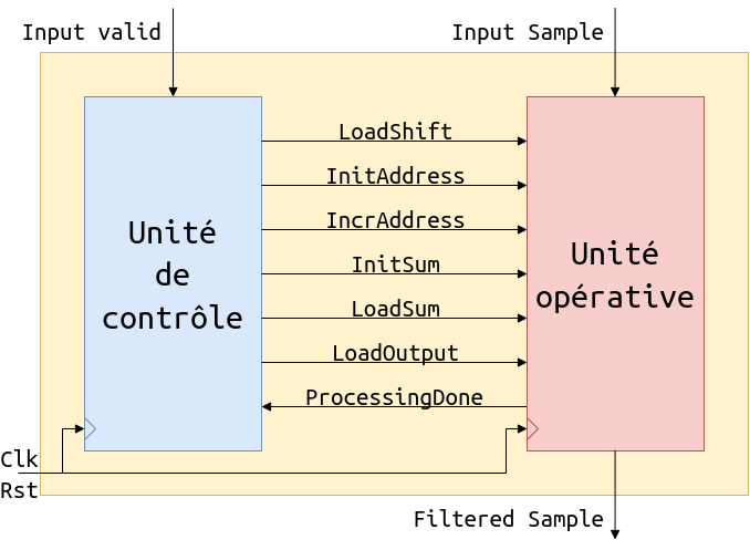
Note
Corresponds to the VHDL file FirUnit.vhd that to eventually be completed
Finite state machine diagram:⚓
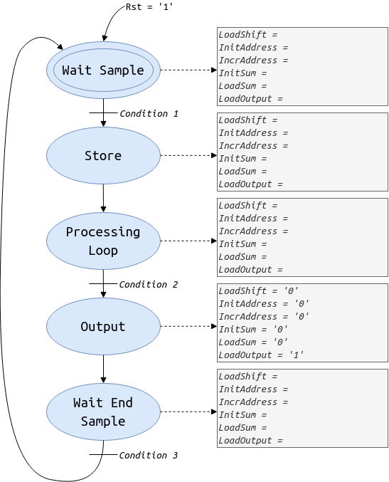
Note
This diagram is to be completed in order to then complete the VHDL file controlUnit.vhd. To do this, you can use the file FSM.drawio available in the git repository, it is the file docs/img/FSM.drawio with the tool https://app.diagrams.net/. Then update the file FSM.png by exporting the diagram FSM.drawio previously updated.
Architecture diagram of the operative unit:⚓
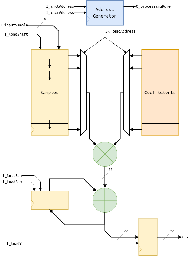
Note
This architecture is to be described in the VHDL file operativeUnit.vhd
Description of the expected work⚓
Preparatory work⚓
Warning
It is mandatory to complete the automaton diagram based on the documents provided. To do this, you need to understand the interaction between control and the operative part. The states are already proposed, you have to provide the transition conditions between the states (the different expressions Ci on the diagram) and the values of the instructions to trigger for each state, based on the example provided for the OUTPUT state.
Work in the classroom⚓
You will use the Xilinx Vivado software to describe and synthesize your circuit based on the files available on the Moodle platform of the UV Électronique, Travaux Pratiques section. During the two sessions, you will complete the provided code of the control and operative parts, then you will test the result of your reflection at each session and deposit on the moodle repository of your room the VHDL files that you will have edited. To validate the effect of the filter, you can test its quantization noise reduction efficiency through different configurations explained in class.
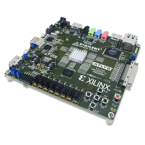
The circuit to be configured is a Xilinx Artix 7 FPGA which is integrated on the Digilent Nexys Video board shown in figure 2.2.4 and including, in addition to the FPGA, many peripherals.
The documentation of the board is available on the Moodle page of the UV Électronique. This documentation is useful to understand the use of the peripherals.
From description to control unit test⚓
Retrieving the gitlab project on https://gitlab-df.imt-atlantique.fr⚓
A git repository has been created for each student on the school's DFVS gitlab instance https://gitlab-df.imt-atlantique.fr. It contains the VHDL sources necessary for the project, scripts to manage the Vivado project, and a compte-rendu.md file to answer the questions. If you work in pairs, choose one of the two, and add your colleague as an owner on the project in gitlab.
First, open a terminal: Ctrl+Alt+T
- Create a directory for the UE Électronique and move into it:
Warning
Remember to adapt the path of the command below to your own needs
1 2 | |
- Clone the git repository locally
Warning
Remember to adapt the link of the command below according to the repository on gitlab
1 | |
git clone command allows you to retrieve the entire git repository with its history of modifications.
You can easily see that this command has allowed you to download with the ls -alsh command in the tp-filtre-etudiant-$USER directory.
Creating a Vivado project⚓
Warning
Never put spaces, accents or special characters in file or directory names! This is true in general, on Windows as well as on Linux. And it crashes Vivado in our case here.
Return to the user's root directory and launch Vivado 2020.2:
1 2 | |
A TCL script is provided to automate the project creation. To use it, you need to:
- go to the Tcl console of Vivado, at the bottom of the window.
- go to the
Projetdirectory with thecdcommand:cd tp-filtre-etudiant-$USER/proj(here you have to manually replace$USERwith your login) - type the command
source ./create_project.tcl
Warning
There should be no accents, spaces or special characters in the path and file name
Note
shell commands cd, ls, pwd are usable in this console
VHDL description⚓
You must replace in the file controlUnit.vhd the parts _BLANK_ with the appropriate VHDL code respecting the automaton that you have completed in preparatory work.
Question filter 1, (answer to be completed in the file docs/compte-rendu.md)
How many processes are used and what are their natures? How do you differentiate them?
Simulation⚓
A "compiled" operative unit is available to simulate and test your description of the control part. Your project must therefore at this stage contain the file operativeUnitIP.v instead of the file operativeUnit.vhd that you will soon modify...
The expected sequence at the output of the filter is (in the form of signed integers):
0 2 3 6 10 15 20 24 26 26 24 20 15 10 6 3 2 0 0 0 1 2 3 5 7 7 8 4 -1 -8 -17 -27 -38 -49 -61 -71 -82 -93 -101 -107 -112 -113 -116.
Simulate the testbench associated with the file tb_firUnit.vhd.
Question filter 2, (answer to be completed in the file docs/compte-rendu.md)
Does the simulation allow you to validate your VHDL description? Justify.
Test⚓
Run the design flow until the bitstream is produced and transfer it to Moodle in the repository provided for your room. It can then be tested on the available board connected to the PC prof. The Line-in input can be connected to any analog source via a 3.5mm jack (output from a smartphone or a PC audio card) and the Line-out output must be connected to a headset or an audio amplifier.
The Nexys VIDEO board is configured so that the 5 switches SW7 to SW3 at the bottom left and the central button BTNC at the bottom right are used.
When the user presses the BTNC button, he can listen to the original audio stream coded on 24 bits and not filtered, otherwise he listens to the audio stream under-quantified at best on 8 bits at the input or output of the filter. The SW7 switch precisely controls this selection. When SW7=ON, the user listens to the filter output, otherwise he listens to the input under-quantified by the filter on 8 bits at best.
Under-quantization is managed by the combination of switches SW6 to SW3. The number of bits removed from the 8 at the input of the filter is coded in natural binary by MSB=SW5 SW4 LSB=SW3 and SW6 allows to select the type of rounding (if ON, to the nearest, otherwise by truncation).
Question filter 3 (answer to be completed in the file docs/compte-rendu.md)
Do you validate the design of the control unit?
From description to test of the operative unit⚓
VHDL description⚓
You must remove the file operativeUnitIP.v and add the file operativelUnit.vhd to the project. Replace the parts _BLANK_ with the appropriate VHDL code respecting the https://tp-vhdl.gitlab-pages.imt-atlantique.fr/filtre/#schema-de-larchitecture-de-lunite-operative
Question 4 (answer to be completed in the file docs/compte-rendu.md)
How many processes are used and what are their natures?
Simulation⚓
Your project must now contain the file operativeUnit.vhd instead of the file operativeUnitIP.v. Then simulate the testbench associated with the file tb_firUnit.vhd.
Question filter 5 (answer to be completed in the file docs/compte-rendu.md)
Does the simulation allow you to validate your VHDL description? If not, what is the problem? How can you fix it? Justify
Test⚓
Run the design flow until the bitstream is produced and transfer it to Moodle in the repository provided for your room. It can then be tested on the available board connected to the PC prof.
Question filter 6 (answer to be completed in the file docs/compte-rendu.md)
Do you validate the design of the operative unit? If not, what is the problem? How can you fix it?