There are instructions in VHDL that are not synthesizable, they are not intended to be used to describe an electronic circuit. The usefulness of these instructions is that they facilitate simulations and the rapid creation of golden models (functional reference model for comparison with the circuit that we want to design).
A test bench is a VHDL file that will only be used to test one or more components. Its VHDL description is not necessarily synthesizable, it is even rarely synthesizable. Indeed we often use non-synthesizable features such as wait and after
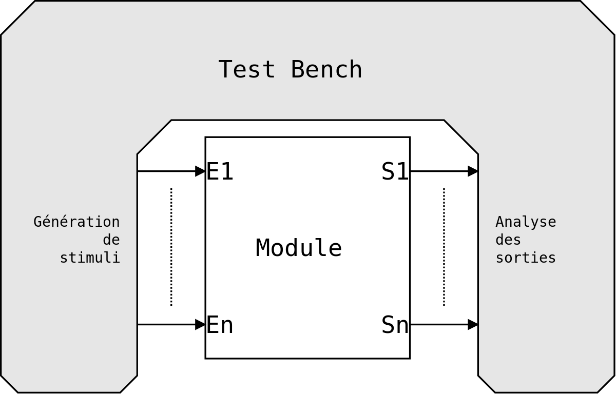
A test bench is a module that has no inputs/outputs, it only includes one or more components, drives their inputs and possibly monitors their outputs.
libraryieee;useieee.std_logic_1164.all;useieee.numeric_std.all;-- exemple de test benchentitytb_Moduleisendtb_Module;architecturearchi_tb_Moduleoftb_ModuleiscomponentModuleis-- module que l'on souhaite testergeneric(G_GenericA:integer;G_GenericB:integer);port(I_Clock:instd_logic;I_Reset:instd_logic;I_Enable:instd_logic;I_Data:instd_logic_vector(G_GenericA-1downto0);I_Address:instd_logic_vector(G_GenericB-1downto0);O_Ready:outstd_logic;O_ResultValid:outstd_logic;O_Result:outstd_logic_vector(G_GenericA+G_GenericB-1downto0));endcomponent;constantCST_GENERIC_A:integer:=12;constantCST_GENERIC_B:integer:=5;signalSR_Clock:std_logic:='0';signalSR_Reset:std_logic;signalSR_Enable:std_logic;signalSR_Data:std_logic_vector(CST_GENERIC_A-1downto0);signalSR_Address:std_logic_vector(CST_GENERIC_B-1downto0);signalSC_Ready:std_logic;signalSC_ResultValid:std_logic;signalSC_Result:std_logic_vector(CST_GENERIC_A+CST_GENERIC_B-1downto0);beginSR_Clock<=notSR_Clockafter7ns;SR_Reset<='1','0'after59ns,'1'after2313ns,'0'after2350ns;instance1_Module:Modulegenericmap(G_GenericA=>CST_GENERIC_A,G_GenericB=>CST_GENERIC_B)portmap(I_Clock=>SR_Clock,I_Reset=>SR_Reset,I_Enable=>SR_Enable,I_Data=>SR_Data,I_Address=>SR_Address,O_Ready=>SC_Ready,O_ResultValid=>SC_ResultValid,O_Result=>SC_Result);process-- process de pilotage des entrees du composant a testerbeginSR_Enable<='0';SR_Data<=(others=>'0');SR_Address<=(others=>'0');waitfor61ns;-- wait : instruction non synthetisablewaituntilrising_edge(SR_Clock);SR_Enable<='1';SR_Data<=std_logic_vector(to_unsigned(111,CST_GENERIC_A));SR_Address<=std_logic_vector(to_unsigned(15,CST_GENERIC_B));waituntilrising_edge(SR_Clock);SR_Enable<='1';SR_Data<=std_logic_vector(to_unsigned(1,CST_GENERIC_A));SR_Address<=std_logic_vector(to_unsigned(7,CST_GENERIC_B));-- ... --endprocess;endarchi_tb_Module;
To simulate a circuit it is sometimes very useful to be able to manipulate text files in a test bench or even in a circuit (before synthesis).
We can use a text file to :
store values to be applied to inputs
store expected internal or output values and compare them to the values present at the output of the circuit
libraryieee;useieee.std_logic_1164.all;useieee.numeric_std.all;useSTD.textio.all;entitytestStdLogicTextioisendentitytestStdLogicTextio;architecturearchoftestStdLogicTextioisfileF_input:textopenread_modeis"../input.txt";fileF_output:textopenwrite_modeis"../output.txt";signalSR_Clock:std_logic:='0';signalSR_reset:std_logic;signalSR_Value1:integer;signalSR_Value2:integer;signalSR_Value3:integer;signalSR_Value4:integer;signalSR_reading:std_logic;beginSR_reset<='1','0'after3ns;SR_Clock<=notSR_Clockafter10ns;process(SR_Clock,SR_reset)isvariabletheline:line;variableV_Value1:integer;variableV_Value2:integer;beginif(SR_reset='1')thenSR_Value1<=0;SR_Value2<=0;SR_reading<='0';elsifrising_edge(SR_Clock)thenif(notendfile(F_input))thenreadline(F_input,theline);read(theline,V_Value1);SR_Value1<=V_Value1;read(theline,V_Value2);SR_Value2<=V_Value2;SR_reading<='1';elseSR_reading<='0';endif;endif;endprocess;SR_Value3<=SR_Value1*SR_Value2;SR_Value4<=SR_Value2+SR_Value1;process(SR_Clock,SR_reset)isvariabletheline:line;beginifSR_reset='1'thenelsifrising_edge(SR_Clock)thenif(SR_reading='1')thenwrite(theline,string'("Op1 = "));write(theline,SR_Value1,left,8);--alignement a gauche, taille minimum de 8 caractereswrite(theline,string'("Op2 = "));write(theline,SR_Value2,left,8);--alignement a gauche, taille minimum de 8 caractereswrite(theline,string'("ResMult = "));write(theline,SR_Value3,right,4);--alignement a droite, taille minimum de 4 caractereswrite(theline,string'(" ResAdd = "));write(theline,SR_Value4,left,9);--alignement a gauche, taille minimum de 9 caractereswriteline(F_output,theline);-- les deux lignes ci-dessous sont expliquees dans la section suivanteassertSR_Value1>SR_Value2report"SR_Value1 = "&integer'image(SR_Value1)severitywarning;assertSR_Value1>SR_Value2report"SR_Value2 = "&integer'image(SR_Value2)severitywarning;endif;endif;endprocess;endarchitecturearch;
There is an instruction that displays messages in the simulator's dialog window.
It is called assert
This instruction allows several levels of criticality: